Friday 21 September 2012

Preparing the AADL environment

In order to develop the SoCiS Architecture Analysis and Design Language, Obeodesigner together with some tools must be available before working with the example.

This post can also be downloaded as PDF from here.


1. Installing the required tools

1.1 Downloading and installing Obeo Designer

The graphical designer will be developed using Obeo Designer (Eclipse based). It can be downloaded here together with a trial license. This is the cornerstone tool for the next steps. After the download is finished, extract the archive and run obeodesigner to see that the tool is working fine.

1.2 Install Xtext 2.2.1

Start Obeo Designer and go to Help menu -> Install New Software -> Select Add. In the new dialog paste http://download.itemis.de/updates/releases/ into the URL field and give the install a name (eg. Xtext). Scroll among the available items and select Xtext 2.2.1.


In the next screen ("Install Details") select "Next", then accept the terms of license agreement and select "Finish". The install procedure should now start. Restart the environment in the end of the procedure.


1.3 Installing Git support

This step is required in order to import the Osate sources. Go to the Help menu of Obeo Designer and select Install New Software. In the dialog window that appears select Indigo http://download.eclipse.org/releases/indigo and after the components list is loaded select from the Collaboration category Eclipse EGit. Click in the next two screens "Next". After accepting the license agreement click "Finish" and accept Obeo Designer's proposal to restart.


2. Importig the required projects

2.1 Import Osate 2 sources

In Obeo Designer select File -> Import. In the newly opened dialog select from the Git category "Projects from Git" click "Next". In the following screen select URI and click "Next". Here provide the github link for the Osate 2 sources, git://github.com/osate/osate2-core.git, and click "Next":


In the next dialog select only the develop branch and click "Next". The develop branch contains the most recent builds. Then select the destination folder for the files. If the path directs to your workspace, you can accept the default settings, otherwise change it to your workspace:


Click "Next" and after the complete project list is loaded, accept the default settings and click again "Next". In the next, last dialog, select - if they are not already selected - all the projects and click "Finish". The workspace should look like in the next screenshot - be sure to be in a perspective where the "PackageExplorer" window is visible (left side of the image):


2.2 Importing the AADL design


  • Select branch master (the only one available) and click "Next"
  • In the following dialog provide the destination folder for the sources. If the folder is already a folder in the workspace, the default settings can be accepted, otherwise select a folder inside the workspace and click "Next"
  • Wait for the list to be populated, and click "i"
  • In the Import Projects dialog select only the org.obeonetwork.dsl.aadl.design and click "i". After this step, the project is imported into the workspace and visible within the PackageExplorer.


2.3 Launch a new Eclipse Application

To launch a new eclipse application click on Run -> Run Configurations. Double click on "Eclipse Application" (or right click on it and select "New") to create a "New_configuration". It be renamed by your desire, eg. "AADL_Example". Make sure that in the "Main" tab, in the "Program run" section, the fr.obeo.dsl.designer.architect.product is selected.

In the "Arguments" tab provide the VM arguments as follows:
-Xms256m -Xmx1024m -XX:MaxPermSize=256m


After the above set up is prepared, click "Run" to start the new eclipse instance.

2.4 Importing the AADL Example


This procedure is very similar to importing the AADL design. make sure to select a destination folder inside your workspace (eg. "aadl_example")The major difference is during the "Importing projects" step, when org.obeonetwork.dsl.aadl.control_processing.example  must be selected (instead of org.obeonetwork.dsl.aadl.design):


After the import procedure is finished, the workspace must look like this:


2.5 Browsing the org.obeonetwork.dsl.aadl.control_processing.example

Opening the "control_processing.aadl" will open the file containing the aadl code. It contains a package, a system together with a basic system implementation, two data type declarations and one process. It is a basic example in order to start the development of the AADL modeler.

The "instances" folder contains an Osate 2 instance of the AADL code example. An instance of the code is required in order to create a diagram. It can be easily done by right clicking inside the System Implementation definition - when the "control_processing.aadl" file is open - and then selecting Instantiate System.

In order to view the existing code with the defined AADL Designer, open the "representation.aird" file and navigate the tree until the final node, "test_diagram"

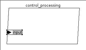
Double click on "test_diagram" will open the current representation. The nodes can be freely moved on the canvas:


Note: The status of the screenshots and examples is the date of publishing this post. Changes in the example or the designer can occur, as it is under development!

Tuesday 4 September 2012

ADELE Example

Before specifying the requirements for the SOCIS AADL designer, I developed a simple demo using the existing TOPCASED AADL Designer, named ADELE. The example is very basic and is based on the specification presented in Table 4-2 of "AADL: An Introduction". The model is not complete but it gives an overview on how to work with the tool, how to create and connect elements. The final purpose is to have AADL code automaticaly generated.

The TOPCASED model files can be downloaded here. The archive contains 3 files:

  • demo_control_processing.aadl contains the generated AADL Code
  • demo_control_processing.adele is the XML model representation
  • demo_control_processing.adeledi contains the graphical model


Summary of the example:
  1. Goal: What does the model contain?
  2. ADELE Project and Diagram set up
  3. Data type declaration
  4. Thread declaration
  5. Thread implementation
  6. Process declaration & implementation
  7. AADL code generation
  8. No .aadl file is generated

1. Goal: What does the model contain?


As in the AADL Introduction paper, a process type with the component type name "control_processing" will be defined. The features of the process are an in data port of type sensor_data and an out data port of type command_data.

For this example two thread types, "control_in" and "control_out", are declared. The implementation of the thread types is "control_in.input_processing_01" respectively "control_out.output_processing_01".

The above thread declarations and implementations are required for the "control_processing" process implementation. The example implementation will be named "speed_control" and contains two thread subcomponents which reference the previously defined thread implementations.

In order to achieve this, we will first define the data types. Next the two thread types will be declared and their implementations designed. Now we are ready to declare the process. Last step is to implement it. When we are so far, code generation is straight forward.

This is how the final model should look like. [Source Table 4-2: A Simplified Example of an AADL Specification]

2. ADELE Project and Diagram set up


Start Topcased in your preferred way: double click on the launcher or from terminal (if working under GNU/Linux). I prefer starting Topcased from terminal because in this way I can see any exceptions that occur.

Create a new "ADELE Project" via "File" -> "New" -> "Other" and then search for "ADELE Project". In the following window name the project "demo" and select "Finish". If the selected perspective is not the "ADELE Perspective" you will be prompted to enable it. Please do so.

You should see the following screen:


Now an ADELE Diagram needs to be created. Righ click on the "demo" inside the "Project Explorer". Select "New" and then "ADELE Diagram". In the following dialog provide the information as follows - be careful to select "Package" in the "Diagram" field:


Inside the "demo" project we previously created, a new folder "demo_ctrl_processing" and two files "demo_ctrl_processing" with the extensions .adele respectively .adeledi are created. Open the "demo_ctrl_processing.adeledi" (by double click on it) and we can move on.


3. Data type declaration


To declare the two data types we need, click on the "Data" component and then click somewhere in the available canvas. Please be careful, as drag-and-drop of the components on the canvas does not work! This will create a data declaration. Name it "sensor_data" and repeat the steps to declare another data type named "command_data". The created objects can be moved after declaration around the canvas by drag-and-drop.


4. Thread declaration


The process of declaring threads is very similar to the "Data type" declaration that we have done earlier. Now select the "Thread" tool inside the "Components" list and then click on a free are in the canvas to the right. Name the thread "control_in". Repeat the process and create the declaration of a second thread named "control_in". The canvas should look like this now (I have moved around the data type declarations):


5. Thread implementation


This step of defining the thread implementation is not as intuitive as the thread declaration and might take some time to figure it out. This is done the following way: the "Thread" component tool is selected (as in the previous step) and then click inside of a thread declaration (for the thread declaration we have clicked on some empty place on the canvas). The thread implementation instance appears inside the thread declaration and the thread declaration name (the string before the ".") is taken over from the thread declaration. Complete the implementation name with "input_processing_01" respectively "output_processing_01"


6. Process declaration & implementation

Process declaration

In this step we will define the process named "control_processing" containing 2 features input and output. They will be referencing the data types declared at step 3. input will reference "sensor_data" while output will reference "command_data".

To declare a process select the "Process" component tool and then click on a free space on the canvas. Name the newly created process "control_processing". Next we need to define the two data port futures for the process. For this inside the "Features" palette select the "In Data Port" and then click on the representation of the process. Name the feature "input". Now the feature is created, but it is not connected to the sensor_data type earlier defined. To do this, in the "ODS" section of the workspace (lower part by default) select "Classifier" and then click the button available in the right side named "Choose a classifier". This will open a dialog were you have the possibility to select the correct data type.

Step 1: define a "In Data Port" feature for the process.

Step 2: select in the ODS section the "Classifier" and
click in the right side on the "Choose a classifier"

Step 3: in the "Classifier explorator" dialog select the sensor_data type declaration

The same steps need to be repeated in order to create an "Out data port". If the out data port is not directly visible inside the Features  palette, then please right click on the small arrow left to the in data port. This will extend the node and the desired data port will become visible:


Process implementation

The implementation of the process is identical to the thread implementation described at step 5: Select the "Process" from the palette and clicked inside the declaration of the "control_processing" process. Name the implementation control_processing.speed_control:


Next, the two thread subcomponents need to be defined: "control_input" referencing the "control_in.input_processing_01" implementation and "control_output" referencing the "control_out.output_processing_01" implementation. This step is very simple once know the workflow of how to do it. It took me some time to figure this out, but afterwards everything went smoothly. By double clicking on the "control_processing.speed_control" implementation, the following dialog is presented:


The user can select either to "Create Behavior Annex Editor diagram" or "Create Process diagram". For this step, the "Create Process diagram" must be chosen. This will open a new canvas containing the in/out ports that are defined in the process declaration - our case "input" and "output". This is a new layer which is hierarchically one level below the declarations and implementations we previously defined. It can be imagined to be "inside" the process speed_control implementation. On the top margin of the canvas the current working level can be observed:


To navigate between these two layers the toolbar buttons to the right can be used. To go to the higher level use the "up arrow". To open the speed control implementation double click on it's block on the top level. A small green arrow in the top-right corner of the implementation box indicates the presence of a lower level:


Having the Process Diagram defined, we need to add the thread sub-components. In order to do this, we need to navigate inside the control_processing.speed_control implementation (double click). Here add two thread instances by selecting the Thread component and clicking on the canvas. Name one of them "control_input" and the other one "control_output". Next they need to be connected to the thread implementations control_in.input_processing_01 respectively to control_out.output_processing_01. To do this, click on one of the newly created threads. We will use for the example the control_output thread declaration. Select in the "ODS" section of the workspace (lower part by default) the Classifier node. In the right window then click on the button "Choose a classifier" and in the presented dialog choose the demo_ctrl_processing::control_out.output_processing_01 classifier. Your screen should look like this:


As a last step before generating code, repeat the process in order to connect the "control_input" thread to demo_ctrl_processing::control_in.input_processing_01. This will end the definition of our first AADL model. We can view the top level:


7. AADL code generation


Having the difficult jobs behind us, we can invoke the code generator. For this, right click on the "demo_ctrl_processing.adeledi" (or .adele) file in the Project Explorer and select "ADELE" and from the submenu click on "generate aadl code". You can keep in mind, that this is not the only way to start the code generation.

A new file named "demo_ctrl_processing.aadl" can be observed in the project explorer. If no file is generated, please look at section 8.


Having a look over the generated code (the file can be opened by double click), it can be noticed that it is similar to the one presented in Table4-2 (in our demo model the comments are missing):


8. No .aadl file is generated


In my situation, after invoking the code generator as described in step 7, no code was generated and I could observe the following error in the console where TOPCASED is started:

java.io.IOException: Cannot run program "/home/TOPCASED/Topcased-5.2.0/plugins/org.topcased.adele.admin_2.6.0.201204031215/usr/LMP/bin.pclinux/sbprolog" (in directory "/home/TOPCASED/Topcased-5.2.0/plugins/org.topcased.adele.admin_2.6.0.201204031215/usr/LMP/sbprolog"): error=13, Permission denied
at java.lang.ProcessBuilder.start(ProcessBuilder.java:1029)
at java.lang.Runtime.exec(Runtime.java:615)
at org.topcased.adele.tools.prolog.actions.PrologExtractionAction.launchAADLGeneration(PrologExtractionAction.java:1057)
at org.topcased.adele.tools.prolog.actions.PrologExtractionAction.createPrologFiles(PrologExtractionAction.java:315)
at org.topcased.adele.tools.prolog.actions.PrologExtractionAction.run(PrologExtractionAction.java:193)
at org.eclipse.jface.operation.ModalContext$ModalContextThread.run(ModalContext.java:121)
Caused by: java.io.IOException: error=13, Permission denied
at java.lang.UNIXProcess.forkAndExec(Native Method)
at java.lang.UNIXProcess.<init>(UNIXProcess.java:135)
at java.lang.ProcessImpl.start(ProcessImpl.java:130)
at java.lang.ProcessBuilder.start(ProcessBuilder.java:1021)
... 5 more

The text "error=13, Permission denied" made me look over the permission of the sbprolog program. I moved to the home/TOPCASED/Topcased-5.2.0/plugins/org.topcased.adele.admin_2.6.0.201204031215/usr/LMP/ folder and could observe, that sbprolog was not marked as executable. A simple chmod 777 sbprolog solved my issue. A new run of the code generator worked smoothly (777 rights are not necessary, just the x bit must be set).